
DIY Car Driving Simulator Soldering Kit Automotive Control System with Gear Shift LCD Display STEM Electronics Learning Project
42,00 € inkl. MwSt., kostenloser Versand
9993 in stock
SPECIFICATIONS
Brand Name: IS
Condition: New
High-concerned chemical: none
Origin: Mainland China
Power Supply: 3.7V 18650 batteries x2 (Not Included)
Type: Logic ICs

 【Car Driving Simulation System】 This DIY kit simulates real car operations through a variety of buttons and lights, including gear shifting, left and right turns, honking, acceleration, deceleration, and lighting changes. It offers an immersive, hands-on experience that brings automotive functions to life. Ideal for STEM learning, school projects, or hobbyists who enjoy building and experimenting.
【STEM Learning Projects】By soldering and operating this electronic kit, teens can explore how car control systems work in a fun and intuitive way. The interactive design not only strengthens practical electronics skills but also sparks curiosity about automotive engineering, making learning both educational and exciting.
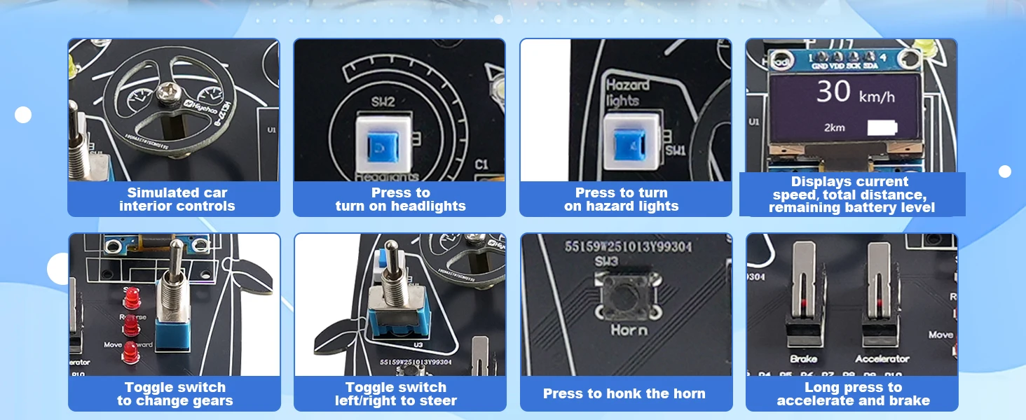
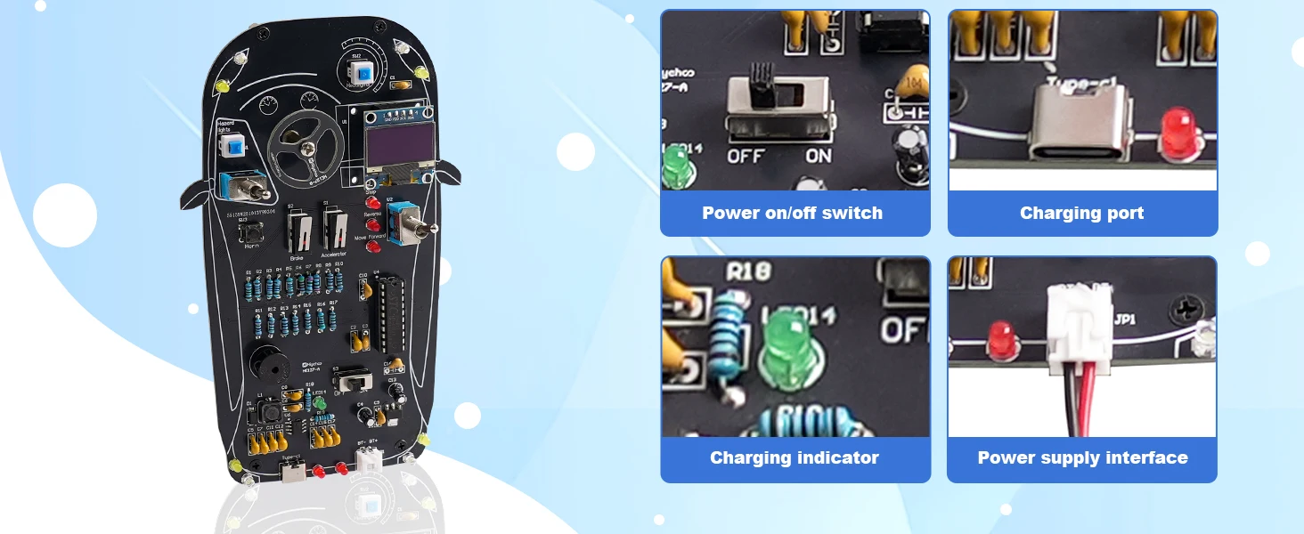
【Features and Functions】The solder kit includes 4 turn signal lights, 2 front headlights, 2 brake lights, and 2 reverse lights. An integrated LCD screen displays the current speed in real time, the three-position toggle switch realistically simulates gear shifting, while the limit switches replicate the actions of pressing the accelerator and brake during driving. Together, these elements create a highly realistic and immersive driving simulation.
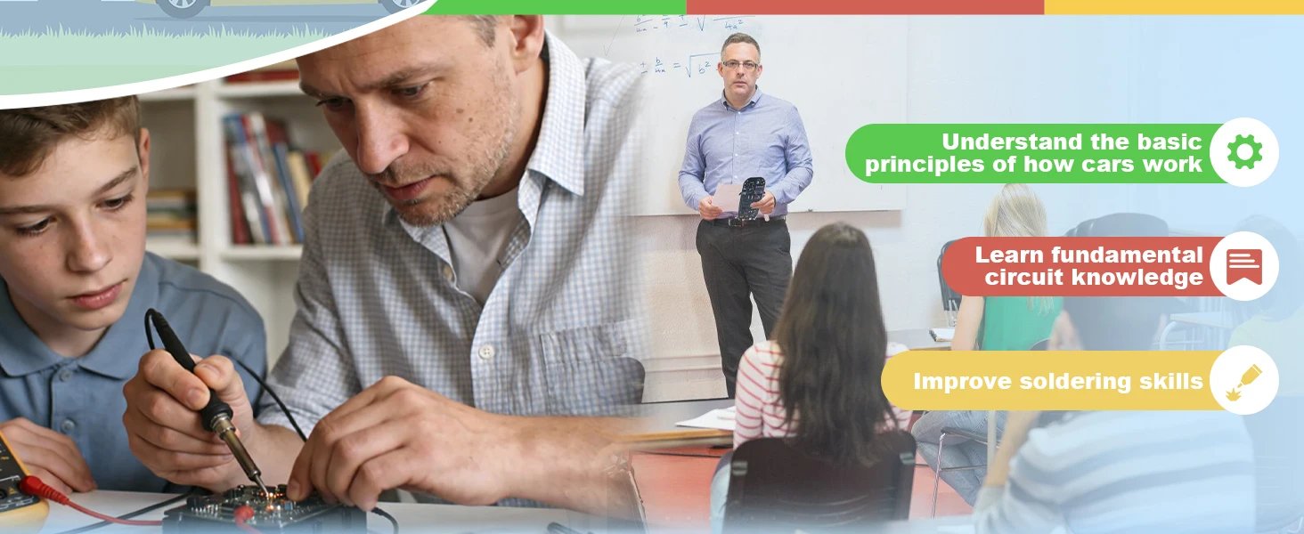
【Soldering Practice Kit】The circuit board features clearly marked and well-labeled connections, making soldering straightforward. Designed for hands-on learning, it helps build practical soldering skills, reinforces core electronics knowledge, and boosts confidence through real assembly experience. An ideal choice for home learning, school STEM programs, and electronics enthusiasts who enjoy learning by doing. Note: Batteries are Not included. Please prepare 2pcs 3.7V 18650 batteries.
【Paper English Manual】Comes with an exquisite paper installation manual which will guide you how to solder this electronics project step by step, ensuring a fun and educational experience for everyone. But please note, this diy soldering kit requires certain foundation of basic electronic theoretical knowledge and welding and hands-on ability.
 Key Circuit Principles Used in This Kit
1、Switch Control Principle
Different car lights (left turn, right turn, high beam, low beam, etc.) are controlled by toggle switches.
Principle: When the switch is closed, current flows to the corresponding LED and turns it on; when opened, the LED turns off.
2、LED Illumination and Current Limiting Principle
The car lights are simulated with LEDs, where different colors represent headlights, taillights, and turn signals.
Principle: A current-limiting resistor is connected in series with each LED to prevent damage.
3、Parallel Circuit Principle
The car light circuits are connected in parallel, so each group of lights can be controlled independently without affecting the others.
4、LED Flashing Principle
Pulse signals generated by the microcontroller drive the LEDs, enabling automatic flashing effects.
5、Asynchronous Boost Battery Charging Circuit
The 5V input is boosted to 8.4V through L1, D1, and the internal power MOSFET of the IC to charge two series-connected batteries.
| Default Title | Default Title |
|---|
Related products
-

Kids Kitchen Toy Set Mini Simulation Household Appliances Toys for Children Pretend Play House Interactive Toys for Girls Boys
30,00 € inkl. MwSt., kostenloser Versand -
Auto-Fahrer-Simulator Lötübungs-Set DIY Auto-Steuerungssystem mit LCD-Display Cooles STEM-Projekt für Schüler und Bastler
37,00 € inkl. MwSt., kostenloser Versand -
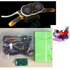
Arcade Super Motorcycle Racing Children’s Simulation Video Game DIY Kit Includes Motherboard with Wires, LED Handlebars Gauges
236,00 € inkl. MwSt., kostenloser Versand -
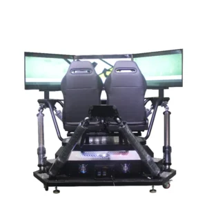
multi-screen dynamic driving car racing emulator game sports driving game console
Original price was: 25.367,10 €.23.675,00 €Current price is: 23.675,00 €. inkl. MwSt., kostenloser Versand -
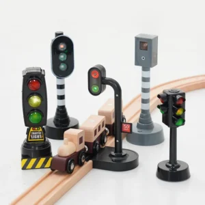
Simulation Traffic Light Toy Traffic Signal Model Road Scene Toys For Kids Compatible with All Major Brands Wooden Railway
Original price was: 16,88 €.16,00 €Current price is: 16,00 €. inkl. MwSt., kostenloser Versand
Reviews
There are no reviews yet.